Error Diagnostics and Trouble Removal of JY500A11 Batching Controller
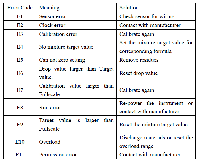
1.Meaning Of Error Code And Simple Solution

2.Fault Detection Method For Load Cell
(1)Checking sensor input and output impedance before wiring. If it has been wired, you should disconnect and then measure it. The input impedance (between Ex+ and Ex-) should be 400±30Ω, (or 700± 30Ω for high-impedance type), and the output impedance (between SIG + and SIG-) should be 350±5Ω, (or 650±20Ω for high-impedance type), if not, you should replace the load cell.
(2)If the weighing value is negative, exchange SIG+ and SIG- for wiring, and then a positive value would be shown;
(3)For power-on testing, the voltage between zero points (namely empty scale) of positive and negative port of sensor input signal should fall within measurement range;
(4)Analog signal is sensitive to interference therefore the load cell cable should use shield wires and as short as possible, kept away from other power lines and control lines.
Check and maintain instrument as following steps in case of wrong weighing display, or unstable display during operation:
(1)Check connectors for moisture and electric leakage.Check connection between the load cell and instrument.
(2)Measure the input and output impedance of load cell before it has been wired, or the internal resistance of the controller would affect measurement results. The input impedance (between Ex+ and Ex-) should be 400±30Ω, (or 700±30Ω for high-impedance type), and the output impedance (between SIG+ and SIG-) should be 350±5Ω, (or 650±20Ω for high-impedance type). if not, please replace the load cell.
(3)Load cell should be replaced if the zero-point voltage is not within the signal measured range.
(4)Load cell should be tested one by one to find out the problematic load cell.
(5)Wiring for the first time, checking if the color of SIG+ and SIG- is matched, or it would lead to unstable display after stressed load cell.
3.Trouble Removal For Load Cell
(1)Check input and output internal resistance of load cell.
(2)Test the voltage between SIG+ and SIG- at the state of empty scale after power on. It should be approximate to the calculated value.
(3)Test each load cell one by one.
(4)Test the instrument with simulator or good-quality weighing hopper.
(5)Check connection between the load cell and the instrument .Check connectors for moisture and electric leakage;
(6)Check if the color of SIG+ and SIG- is matched. Test each sensor separately.
(7)Check wiring between sensor and instrument, and check whether connector and contact is well connected .
4.Automatic Operation Failure
Please follow the below steps if the instrument fails to automatic operation:
(1)Turn "Manu./Auto." switch to "Auto.", access automatic operation interface.
(2)Observe the displayed weight value on the screen. Long pressing
【ENT】can zero the current displayed weight value. If it is failed, reset parameter "ZeroRange" (increase its setting value), or remove sediments and deposits in the weighing hopper, or both.
(3)Take following procedures if failing to start operation after pressing"Run":
1)Check the wiring;
2)Check the formula and confirm formula number;
3)Check if there is any error prompt.
5.Removal Of Common System Fault

Take following procedures to remove system faults:
Step 1: Check the instrument display , if no, check if the instrument power is damaged.
Step 2: Turn “Manual/Automatic” Switch to “Manual”, press down the button on the console and observe corresponding relay and checking AC contactor is on. If not, check if the connector is connected stably on the console; check whether it is damaged (measure with multimeter whether the input port of AC contactor is provided with 220VAC), or check whether the wiring is well connected from output to AC contactor and check whether the fuse is damaged or well connected.
Step 3: If it works normally in above two steps, check air source and observe whether the barometer displayed a value (about 0.4-0.6Mpa). Step 4: If the above checking is normal,
For pneumatic mechanism: check if there is 220VAC output from console to electromagnetic valve, if any, electromagnetic valve may be damaged and should be replaced; if not, the wiring from console to electromagnetic valve would be disengaged or with bad connected and should be connected again.
For Electrical discharging: check whether the AC contactor output is 380VAC. If it is normal, check whether the motor is damaged.
Method: Detected motor may be connected to the output of AC contactor which is in sound condition and observing whether it runs.
Shen Zhen Zhuohe Instrumentation Co.,Ltd was founded in year of 2002.We specialize in providing BATCHING CONTROLLER,BELT SCALE CONTROLLER,PACKAGING CONTROLLER and WEIGHING TRANSMITTER.
If you are interested in our products, welcome to contact us via email.

